Keywords: Reflection, Electric signal, Impedance, Short circuit, Open Circuit
Reflection of Electric Signals in Conductors
Reflection of electric signals demystified.
Our universe is governed by laws. All scientific phenomena 'subconsciously' follow all laws that govern them. One fascinating thing about these phenomena is that you can explain them using different points of view. This, I think, is the reason why Albert Einstein was seeking to find a unified field theory that would combine his theory of gravitation and electromagnetism during the last three decades of his life. Electromagnetism in itself is a unification of two phenomena (electricity and magnetism) that were thought to be unrelated. First proposed by Michael Faraday, then theoretically formulated into the four electromagnetic equations by James Clerk Maxwell and later proved experimentally by Heinrich Hertz, electromagnetism combines at least three laws; Faraday's, Coulomb's and Ampere's laws.
Now, the reason I started with all that jargon was due to an interesting observation that I made while I was studying literature on Time Domain Reflectometry (TDR). Multiple approaches were used to explain reflection of electric signals in cables. Examples of the approaches used were circuit theory, principle of conservation of energy and charge, RADAR and waves in water. This blog combines some of these concepts to explain reflection of electric signals.
An electric signal travelling down an electric cable gets reflected wholly or partially when it encounters impedance discontinuities in the cable. To explain how impedance discontinuities, cause reflection of an incident signal, let's state some laws and theorems.
i. Finite speed of electricity
When one switches on the lights in a dark room, the lights come on instantaneously (some lighting technologies may take time). This can make one believe that electricity travels at an infinite speed. However, electricity has a finite speed. Electricity travels in an electric cable at the speed close to the speed of light in vacuum. The ratio of the speed of electricity in a conductor to that of light in a vacuum is called the velocity factor, .
$$VF = {v \over c}$$Where is the velocity of electricity in a cable and is the speed of light in vacuum.
ii. Maximum power transfer theorem
Given a DC source, , with a source resistance, , connected to a variable load, , the maximum power transfer theorem states that the maximum power transfer to the load occurs when .
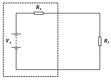
Figure 1: DC source with an internal resistance connected to a load with a resistance .
iii. Principle of conservation of energy
The principle of conservation of energy states that the energy in a closed system remains constant. Loosely stated, energy can neither be created nor destroyed; it can only be transformed from one form to another.
iv. Kirchhoff's laws
Kirchhoff's laws are laws formulated by Gustav Kirchhoff that describe current in a node and a voltage around a loop. There are two Kirchhoff's laws, i.e., Kirchhoff's current law and Kirchhoff's voltage law. Kirchhoff's current law states that the current entering a node equals the current leaving a node. Kirchhoff's voltage law states that the sum of potential differences around a closed loop is zero.
Having stated these laws, now let's explain how impedance discontinuities cause reflection of incident signals. We will do this by using an open circuit and a short circuit.
Open circuit
Consider a pulse generator connected to an open circuit as shown in Figure 2.
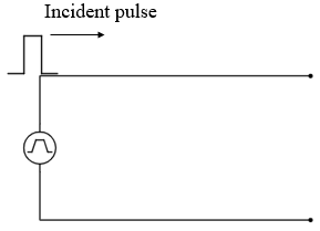
Figure 2: A pulse generator connected to an open circuit.
Let's assume the conductors are lossless (zero impedance). When a pulse is applied at the input end of the conductor, it is unaware of the status of the cable's terminal (due to finite nature of the speed of a signal) and so charges travel up to the end of the cable where they meet infinite impedance. With nowhere to go, the principle of conservation of charge/ energy requires that there should be an equal amount of charges travelling in the opposite direction. This is basically Kirchhoff's current law. To drive these charges in the opposite direction, a voltage in phase and equal to that of the incident pulse is needed and this forms the reflected pulse. The reflected pulse adds up with the incident pulse (constructive interference) and, therefore, twice the incident signal appears at the end of the cable. The reflected pulse travels back cancelling the incident current due to the incident pulse resulting in net zero current in the circuit (by definition an open circuit has no current).
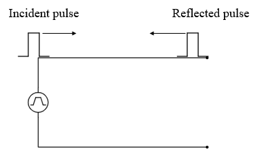
Figure 3: Incident and reflected signals in an open circuit.
Short circuit
Now let's consider a short circuit setup. Consider a pulse generator connected to a short circuit as shown in Figure 4.
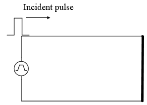
Figure 4: A pulse generator connected to a short circuit.
Reflection in a short circuit can be explained using the same approach used for open circuit. For a short circuit, the voltage needs to be zero at the end of the line from Kirchhoff's voltage law. For this to happen, a negative going pulse is required. The negatively travelling pulse results in a negatively flowing current. The reflected pulse cancels out the incident pulse and the reflected current adds up with the incident current from the principle of duality in circuit theory.
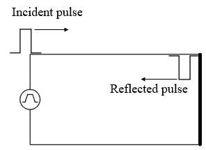
Figure 5:Incident and reflected signal in a short circuit.
If you think about it, an ideal short circuit means a load with zero impedance. From Ohms' law, the current, , flowing through the load will be infinite, i.e.,
$$I = {V \over 0} = \infty $$An infinite current means infinite power, , from the relation:
$$P = VI$$This goes against the principle of conservation of energy since it means energy is being created. But with the negative going pulse, the voltage at the short circuit becomes zero and hence the power (heating effect of an electric current) is zero for an ideal short circuit.
Arbitrary impedances
In the two outgoing cases, we have considered an open circuit (infinite impedance) and a short circuit (zero impedance). We also assumed the conductors used to be lossless. In practical cases, circuits are terminated using loads of definite impedance and the conductors used are not lossless. A uniform conductor is described using its characteristic impedance, , which is the impedance per unit length.
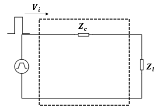
Figure 6: A transmission line model.
For a line that is terminated by a load with the same impedance, , as its characteristic impedance, there is no reflection (from maximum power transfer theorem). Any load with an impedance that is not equal to the characteristic impedance of the line will result in reflection of an incident signal. The reflection coefficient, , of a circuit is given by:
Where: is the voltage magnitude of the reflected signal and is the voltage magnitude of the incident signal. Loads with impedances higher than the characteristic impedance of the cable result in reflections that are in phase with the incident signal and the vice versa is true. Open circuit and short circuit have the optimum reflection coefficients of and respectively. Therefore, the magnitude and phase of the reflected signal depends on the magnitude of the impedance discontinuity.