Keywords: Sensor power management, Solar power, Ecological data collection, Long term deployment
DSAIL Power Management Board: Powering the Raspberry Pi Autonomously Off-the-Grid
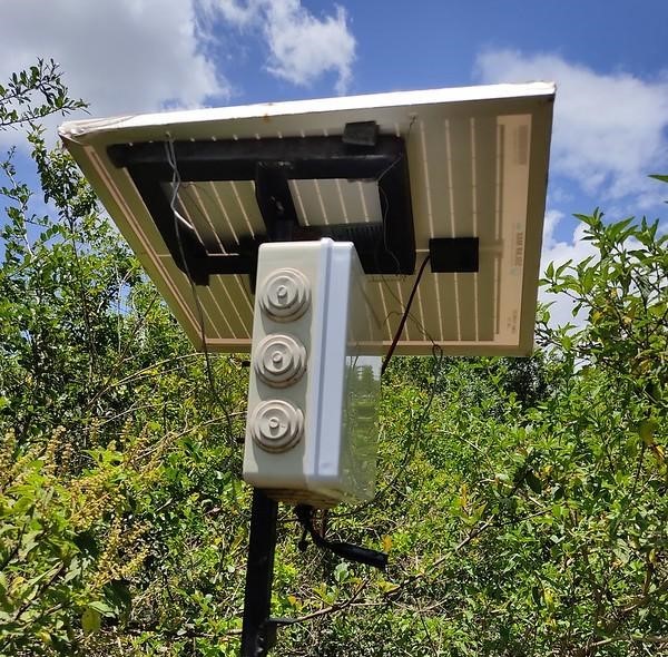
A Raspberry Pi based acoustic sensor.
Introduction
One of the most crucial factors when designing sensors to deploy in the field is power. The main challenge is usually to lengthen the time of operation of the sensors since most of them are battery powered.
The Raspberry Pi is an inexpensive and powerful single board computer that finds many applications in sensor systems. It can be configured to work with high-specification hardware and consumes less power. When designing a Raspberry Pi system to deploy in the field, the problem of powering the system needs to be handled carefully. Like in normal computers, there is constant reading and writing on to the storage of the Raspberry Pi. This means that care needs to be taken when shutting down the Raspberry Pi. Abrupt disconnection from power may result in corruption and hence loss of data in its storage.
When designing the DSAIL Bioacoustics System. (that is based on the Raspberry Pi single board computer), the first step was to design a circuit to power the Raspberry Pi intelligently. The system is powered by a solar panel and a lithium battery. In the following sections, we will look at the design of the circuit.
Requirements of the design
The circuit design for powering the Raspberry Pi was to meet the following requirements:
- Provide the Raspberry Pi with a constant voltage (5.1V),
- Enable the Raspberry Pi to monitor the voltage of the battery,
- Provide the Raspberry Pi with the ability to shut down the system,
- A mechanism to wake the system after the battery has recharged
Provide the Raspberry Pi with a constant voltage
The Raspberry Pi operates at a voltage of 5.1V. For proper performance of the Raspberry Pi, it is necessary to provide it with the rated voltage. Our system uses a 3.7V lithium battery. To obtain 5.1V from the battery, we used a boost converter to step up the dc voltage.
Enable the Raspberry Pi to monitor the voltage of the battery
Lithium cells are not constant voltage generators. The voltage of a cell drops as charge is being drawn from it. Using this fact, we can monitor the state of charge (SOC) of the battery. Monitoring the voltage of the battery was a crucial requirement for our design. One reason is to ensure that the Raspberry Pi does not shut down due to the battery getting drained. The other reason is to lengthen the life of the battery by preventing over discharge. The board employs the MCP3008 analog to digital converter (ADC) to enable the Raspberry to read the voltage of the battery. The Raspberry Pi lacks an onboard ADC hence cannot read the voltage which is an analog quantity. The ADC samples the voltage reading of the battery and feeds a digital form of the reading to the Raspberry Pi through the GPIO pins. Using the voltage reading, the Raspberry Pi is able to monitor the SOC of the battery and shutdown the system whenever the voltage drops to the rated cut-off voltage of the battery. This ensures that the battery never goes below the rated cut-off voltage (2.8V for our battery) hence lengthening its life cycle.
Provide the Raspberry Pi with the ability to shut down the system
When the voltage of the battery drops to the cut-off voltage, the entire system needs to be shut down. This should be done in a way that accommodates for safe shutdown of the Raspberry Pi. To achieve this, we used a combination of a 555 timer and a decade counter. The timer is connected in astable mode to produce a square wave of period 4s. The output of the timer is fed to a decade counter. The decade counter tenth output pin is used to trigger the shutdown of the entire system. The aim of this setup is to delay the disconnection of the system from power to give the Raspberry Pi enough time to shut down in the conventional way.
When the Raspberry Pi has 'decided' to shutdown, it triggers a thyristor that connects the 555 timer and decade counter circuit to power. The timer starts producing pulses that are counted by the decade counter. On the tenth pulse, the tenth pin of the decade counter disconnects the entire system from power. The decade counter's output triggers a transistor that withdraws momentarily the anode current of the thyristor connecting the entire system to power hence shutting the entire system. The entire process of shutting down the entire system takes approximately 40s since we count ten pulses of period 4s each before the system is shut down. This gives the Raspberry Pi more than enough time to shutdown safely before the power is disconnected.
A mechanism to wake the system after the battery has recharged
After the system has shut down, the battery is will be charged by the solar panel. The system should then wake up and start operating. To achieve this, we incorporated a DS3231 real time clock(RTC) on the board. The RTC is equipped with an alarm interrupt that can be utilized to schedule the wake up of the system. Before the Raspberry Pi shuts down, it sets the alarm of the RTC to schedule for the time it should wake up. When the time of the RTC matches that of the set alarm, the alarm interrupt is used to trigger the system to wake it up. The RTC is also helpful in setting the time of the Raspberry Pi since it lacks an onboard RTC. This is especially important for timestamping the saved bird audio recordings.
Design of the DSAIL Power Management Board
Guided by the above requirements, we designed the DSAIL Power management board using basic electrical and electronic components. The design was first carried out on Proteus software. Proteus is a simulation software that is used in the design of electrical circuits and printed circuit boards (PCB). Use of simulation software in designing helps one to analyse the performance and suitability of a design without actually making the prototype using the actual components. This makes it cheaper, faster and increases flexibility of the design process.
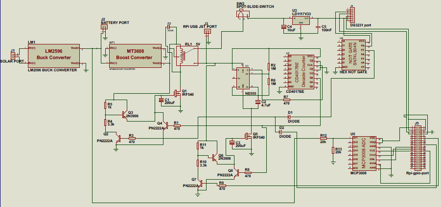
Figure 1: Schematic diagram of the DSAIL Power Management Board circuit.
After designing the circuit on Proteus, we acquired the components that were required for the design. The components were obtained from Pixel Electric Engineering Ltd and Nerokas Engineering Solutions. The circuit was first prototyped on a breadboard. Once we were comfortable with design, we proceeded to making a printed circuit board for the circuit.
For the PCB design, we used KiCad software. KiCad enables one to design a schematic of an electronic circuit and then convert it to a PCB design. The PCB design is then then exported as a PDF and printed on an A4 paper with toner (photograph paper, mate). The toner is then placed on the copper clad board face down and then the printed tracks of the PCB design are transferred to the board using a hot iron box. Using special chemicals, the copper on the board is removed leaving only the parts that have been covered by the toner. This forms the copper tracks for electrical conduction of the board. This process is called etching.
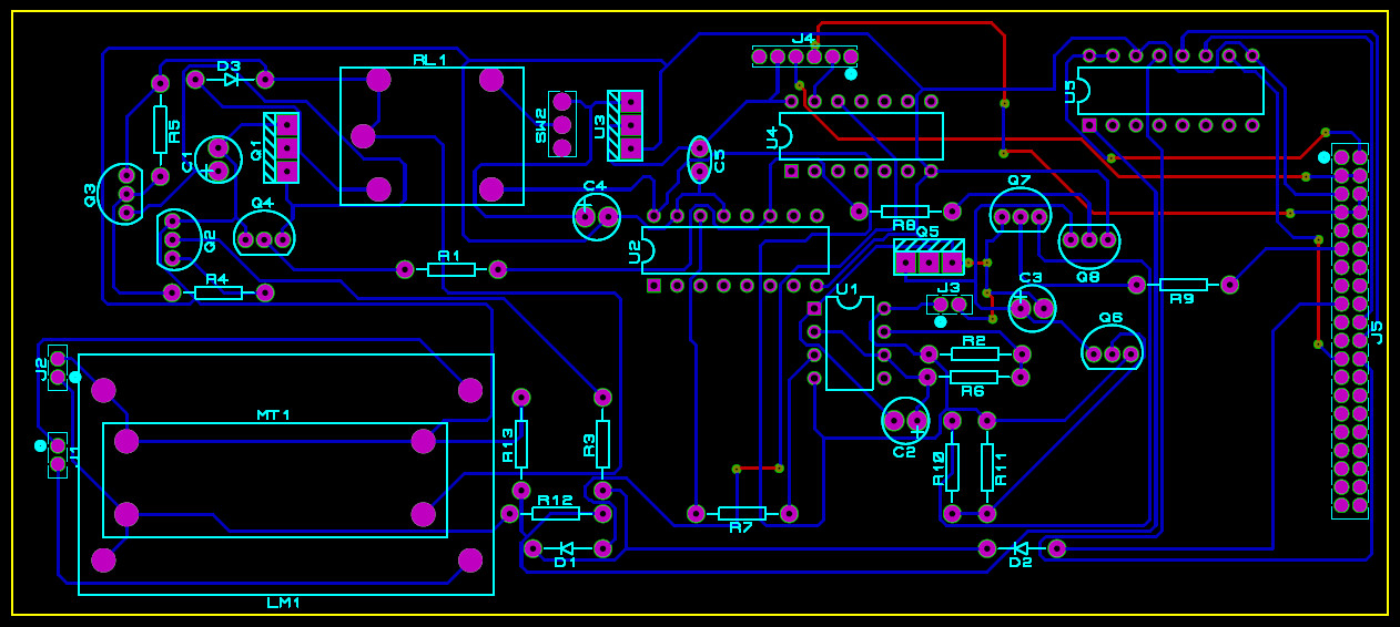
Figure 2: PCB design of the DSAIL Power Management Board circuit.
After the etching process is complete, the components can now be placed on the board and soldered. We transferred the components and soldered them carefully. We then tested the board and it successfully powered our Raspberry Pi as expected. It was an achievement!!! Figure 3 below shows the DSAIL Power Management Board.
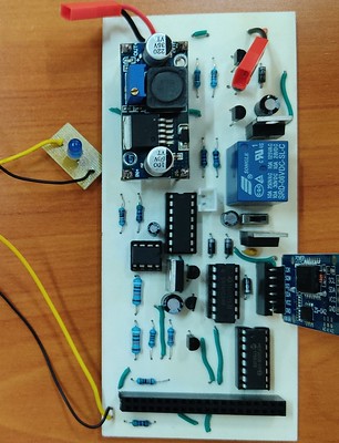
Figure 3: DSAIL Power Management Board.
A program was also written on the Raspberry Pi to control some components of the board. The program enables the Raspberry Pi to read the output of the MCP3008 ADC, set the alarm of the RTC and to initiate the process of shutting down the system.
System Performance
After developing the system, we carried test both in the lab and in the field. Figure 4 below shows the DSAIL Power Management Board and a 6,600 mAh, 3.7 V lithium battery being used to power a Raspberry Pi based acoustic sensor.
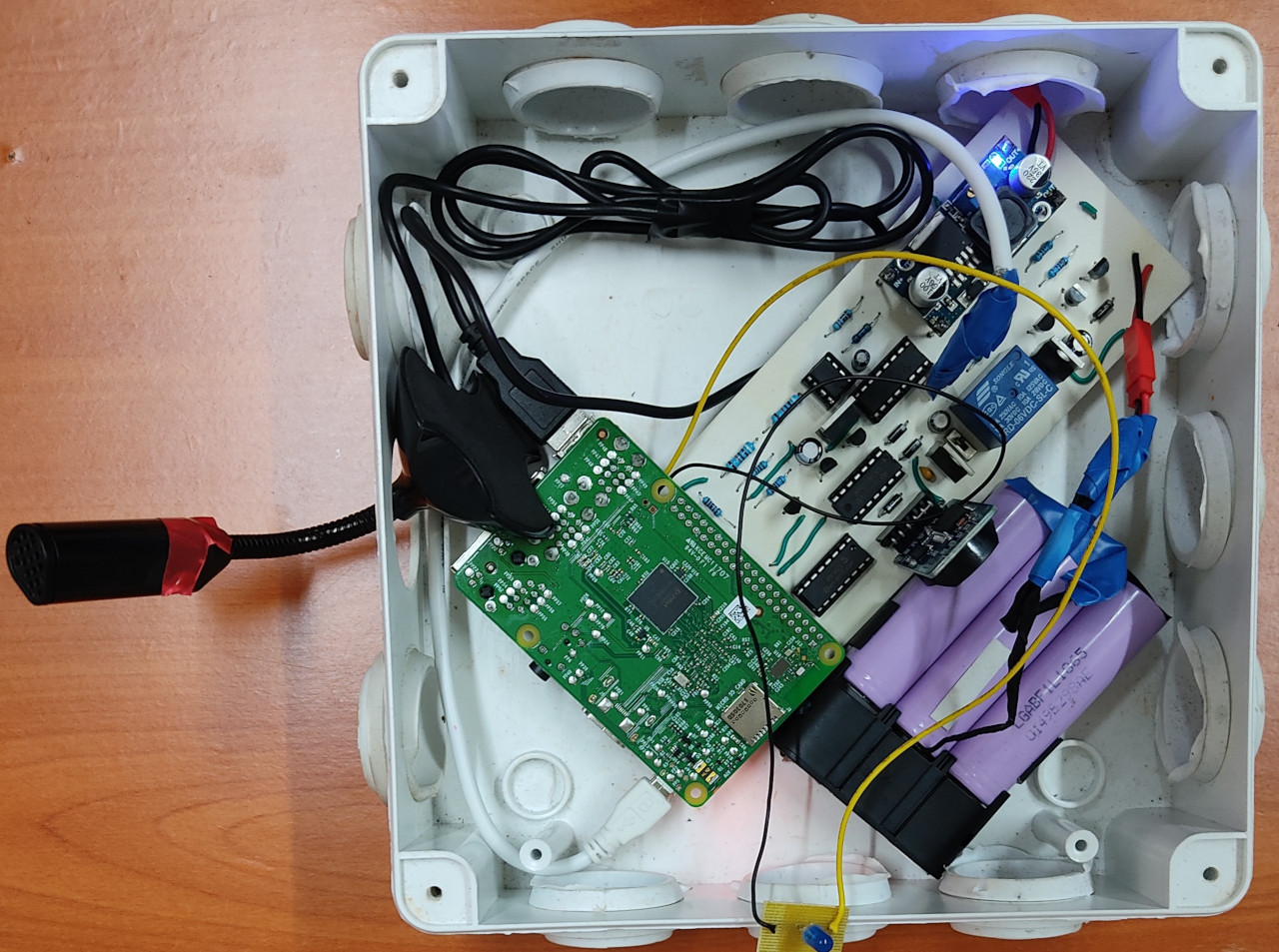
Figure 4: The DSAIL Power Management Board and a 6,600 mAh, 3.7 V powering the Raspberry Pi.
We have deployed the system for testing and also for collecting acoustic data of birds. The system performed efficiently during the initial deployments at Dedan Kimathi University ofTechnology. The system was set to operate during a certain window of time in a day due to power constraint. The system wakes up at 5 am and operates up to 11 am when birds are most active and then shuts down for the battery to charge. During this period, the system was able to shut down as expected. The Raspberry Pi was also able to successfully monitor the voltage profile of the battery when the system was operating. Figure 5 below show the voltage profile of the battery during the deployment at Dedan Kimathi University of Technology Conservancy from 16th to 20th November, 2020.
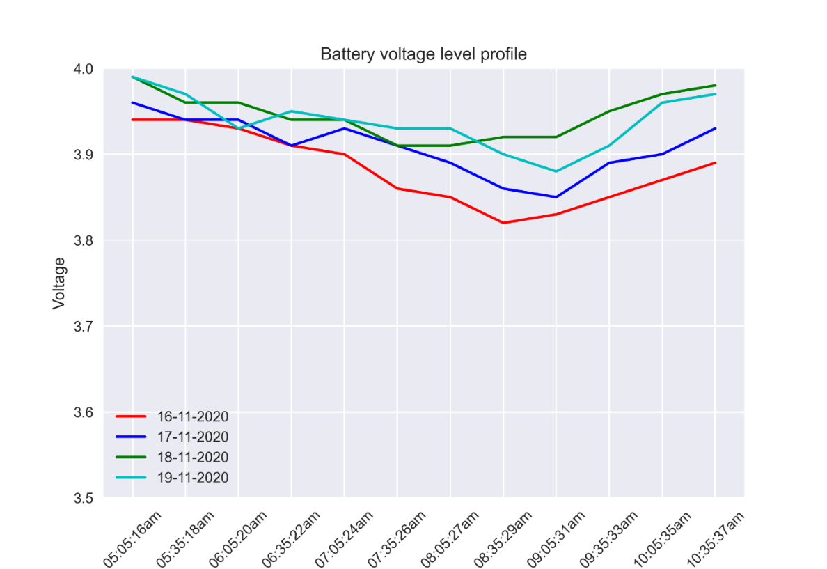
Figure 5: The voltage profile of the battery from 16th to 17th November, 2020.
From figure 5 above, we can observe the discharge and charging of the battery. It can also be observed that the voltage of the battery always started at a value higher than the voltage before the system shutdown in the previous day. This is a proof that the battery was being charged when the system shut down
Conclusion
Power is one of the most crucial factors to consider when designing sensors to deploy in the field. It is even more important when it comes to systems that are based on the Raspberry Pi. Care needs to be taken to ensure that the Raspberry Pi does not shut down due to batteries used to power it getting drained. At DSAIL, we designed the DSAIL Power Management Board to power the Raspberry Pi intelligently. The board ensures that the Raspberry Pi can monitor the battery and shutdown whenever the battery voltage drops to the cut-off voltage. The board also enables the Raspberry Pi to schedule the time it intends the system to wake up after the battery has been charged by a solar panel. Therefore, the DSAIL Power Management Board is an efficient design for powering the Raspberry Pi in the field.
Glossary
555 timer- is one of the most used integrated circuit (IC). It is used together with an external RC (resistor-capacitor) circuit to produce a variety of waveforms.
Breadboard- A solderless device that is used in developing electronic circuit prototypes for testing.
Cut-off voltage- the voltage at which the battery is said to be completely discharged. Further discharge beyond this point will shorten the life of the battery or destroy it completely.
Decade counter- a digital electronic circuits that is used to count pulses. Each pulse applied to its clock increments or decrements the number in the counter. A decade counter can count up to 10 pulses.
State of charge (SOC)- the ratio of current charge in a battery to its rated capacity. It is expressed as percentage (0% to 100%). A full battery will have a SOC of 100%, while a fully discharged battery will have a SOC of 0%.
Thyristor- also called a silicon controlled rectifier (SCR) is a three terminals (anode, gate, cathode) solid state device that is turned ON by applying a gate signal on its gate. The SCR remains ON even after the gate signal is withdrawn (latching) provided the anode current is above the holding current (threshold value of current below which an SCR turns OFF). One of the ways of turning the thyristor off is by withdrawing the anode current momentarily.
Publications
[1] G. Kiarie and C. wa Maina, "Raspberry Pi Based Recording System for Acoustic Monitoring of Bird Species," in 2021 IST-Africa Conference (IST-Africa), 2021. View
[2] G. Kiarie, J. Kabi and C. wa Maina, "DSAIL power management board: Powering the Raspberry Pi autonomously off the grid," HardwareX, vol. 12, p. e00337, 2022. View
Technical Reports
[1] G. Kiarie and C. wa Maina, "Raspberry Pi Based Recording System for Acoustic Monitoring of Bird Species," DSAIL Technical Report (DSAIL-2020-001), 2020.